Digital Twins are never identical
An initial assumption for a digital twin might be that it's a direct copy of the sensor and actuator values from a device in the real world. When the real-world object changes value the twin changes value and when the twin value is changed by software the real-world device turns a light or pump on or off to match.
This is unfortunately a gross simplification for what really needs to happen. The ideal digital twin is far more complex and the unreliable network between them complicates matters further. Based on my experience building digial twins (which goes back a long way before they were given that name) here are the main things you need to consider:
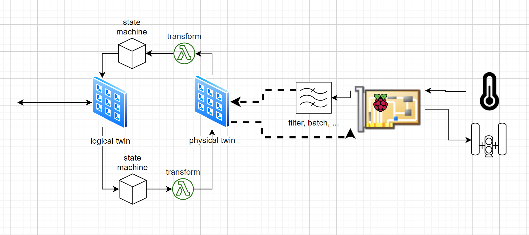
Separate 'logical' and 'physical' device twins
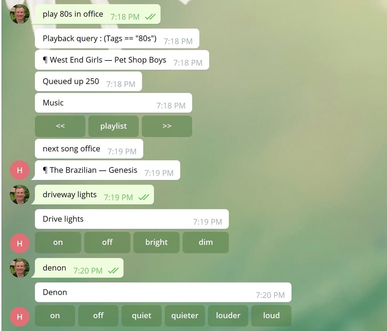
Early on in my home automation system evolution I decided to separate logical devices from physical devices. For example, the 'Hall Light' is a logical device, it will always be called 'hall light' or one of its alternate names, it will always be in the hall and it will always have a brightness from 0.0 to 1.0. Early on there was an X10 device 'A8' that was the switch for the hall light. It had 256 brightness levels 0x00-0xff. Later it was replaced with a Lutron Caseta light switch with levels from 0 to 100. Because I modeled the logical and the physical devices separately I have been able to maintain many years of data for each light switch with a consistent name and a canonical brightness value even though the physical device has changed.
Separate Desired state and Actual state
You may want to turn a light on from software but whether or not that light turns on is another matter. Tracking the logical device state 'hall light on' and the physical device state 'relay=0' is essential for understanding (i) whether the device is functioning and (ii) whether a change in the physical device state was triggered by the system or by a human pressing the light switch. The latter indicates that there is someone on the room right now pushing the switch and asking for manual control over the light, the former means the system is still in control of the light. Separating the logical device and the physical device is one way to achive this separation of desired vs actual state.
Timing and reconciliation
A naive implementation would see the logical device change state and send a request to the device, just once, to change state. There are many things that can go wrong in between and even on the most reliable light switches, occasionally they miss a transmission. A better approach is to continually ensure that the physical light matches the logical light sending commands to update it as necessary, or polling it to check that it has the desired state. Not all devices can do this, some are 'fire-and-forget', for these you may choose to repeat an on/off command some time later to ensure that the light really is on/off.
Values need to be mapped
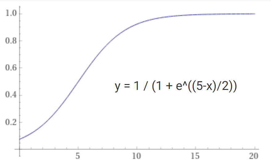
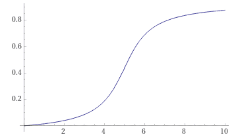
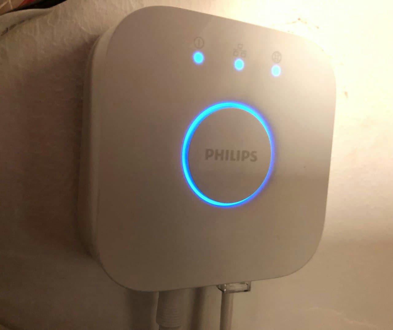
Most devices quantize the values sent to them into discrete stepped values. A light might only have 100 brightness levels, a multizone amplifier may have only 40 levels and a thermostat might internally have 0.1 degrees resolution in farenheit. Meanwhile our logical device wants to track a consistent, canonical 0.0 - 1.0 for all brightness and volume levels and it wants to use Celcius throughout for temperatures. This is a problem because when we set the brightness to 0.123 that might translate to 12 on the device itself and would come back as 0.12 when we convert it back. Our system would see that as a change in brightness and would assume, incorrectly, that someone pushed the switch. An essential part of the ideal digital twin is a mapping function that maps logical values to and from physical values and can determine when they are the same. This could be as simple as rounding the value to an int or it could involve a curve or other functional mapping and a quantization step. Mapping color values to and from Phillips Hue and RGB LED strips is another example of value mapping.
Sensor data needs filtering
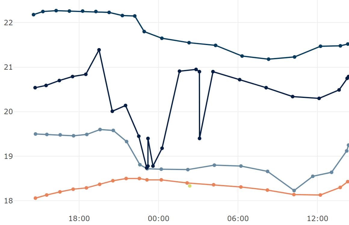
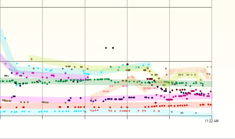
Devices typically do not present smoothly changing sensor values. Most have low-amplitude noise on them and sometimes they suffer large random glitches that need to be filtered out. A digital twin will need to implement filtering including rejecting spurious values and perhaps a Kalman filter. Often you will do this at the edge in the device itself as it reduces the bandwith needed to the server (no need to transmit the noisy values). Even when it does happen at the edge you may want to change the parameters for that filtering to the device through its digital twin.
Sensor data needs rate limiting
In addition to filtering the sensor values you may wish to limit how much data is sent to the server over time, for example, only send changes when the temperature changes by more than 0.1 degree celcius or limit changes to no more often than every five minutes. But you will also need to make sure the device sends some data regularly to indicate that it is still alive even when the value is not changing. A delta, min interval and max interval setting are useful in these cases but even smarter data compression is possible.
Time of observation
This is a hard one because the sensor or gateway may or may not have a reliable clock or we may be buffering data on the device or storing it offline for later sending to the server when a connection is made. Should we use the time of arrival of the message, or the time it was captured by the device? A Raspberry Pi-W without an RTC Module will drift by several seconds during a day between connections to an NTP server so we can't rely on the device time being accurate. One approach is to send both the recorded time and the local time (now) with each message to the server, the server can adjust the recorded times based on the difference in time between the two values and its own more reliable clock. There is no easy answer to this problem but you should consider it in the design of your digital twin.
Metadata
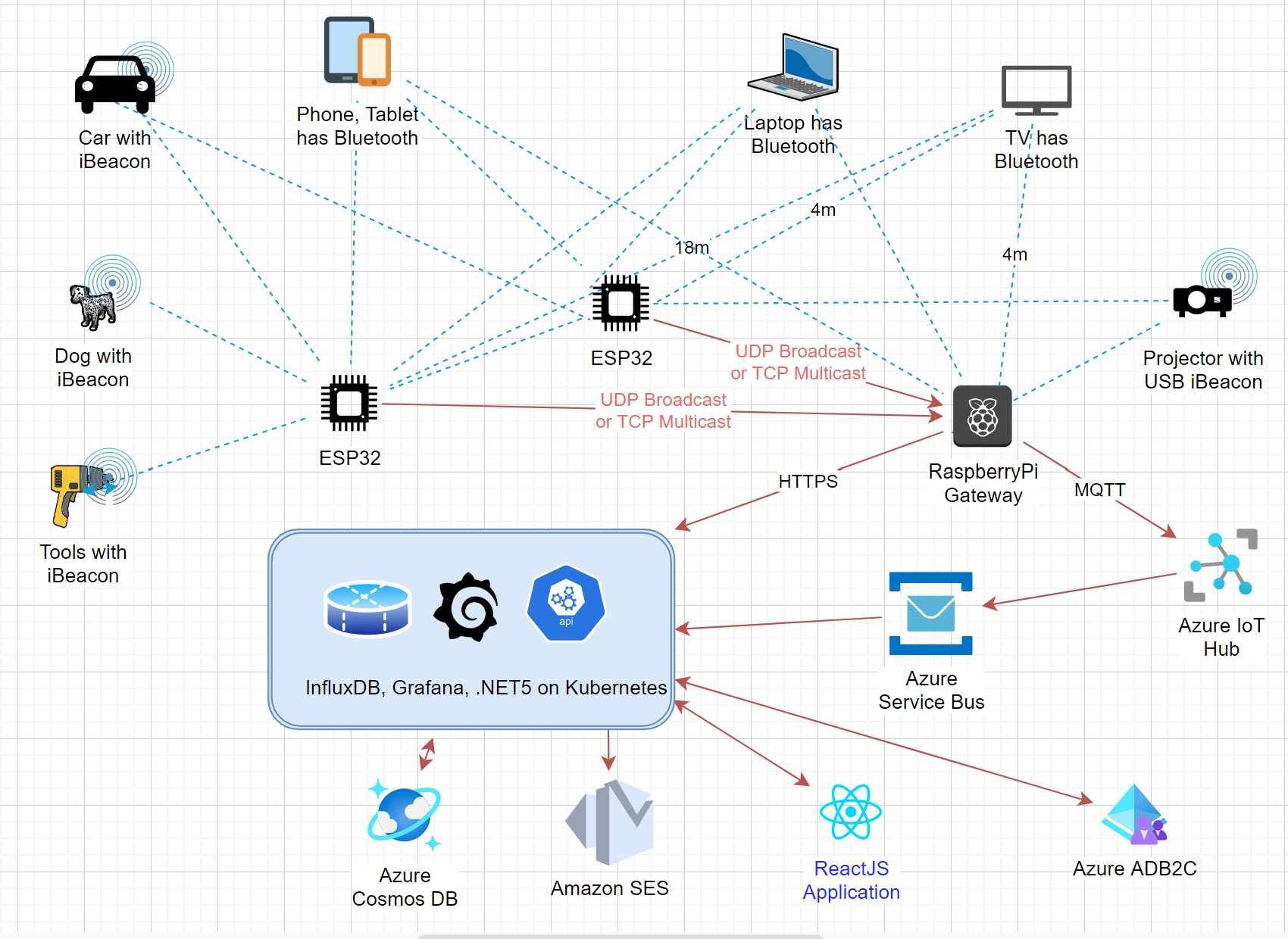
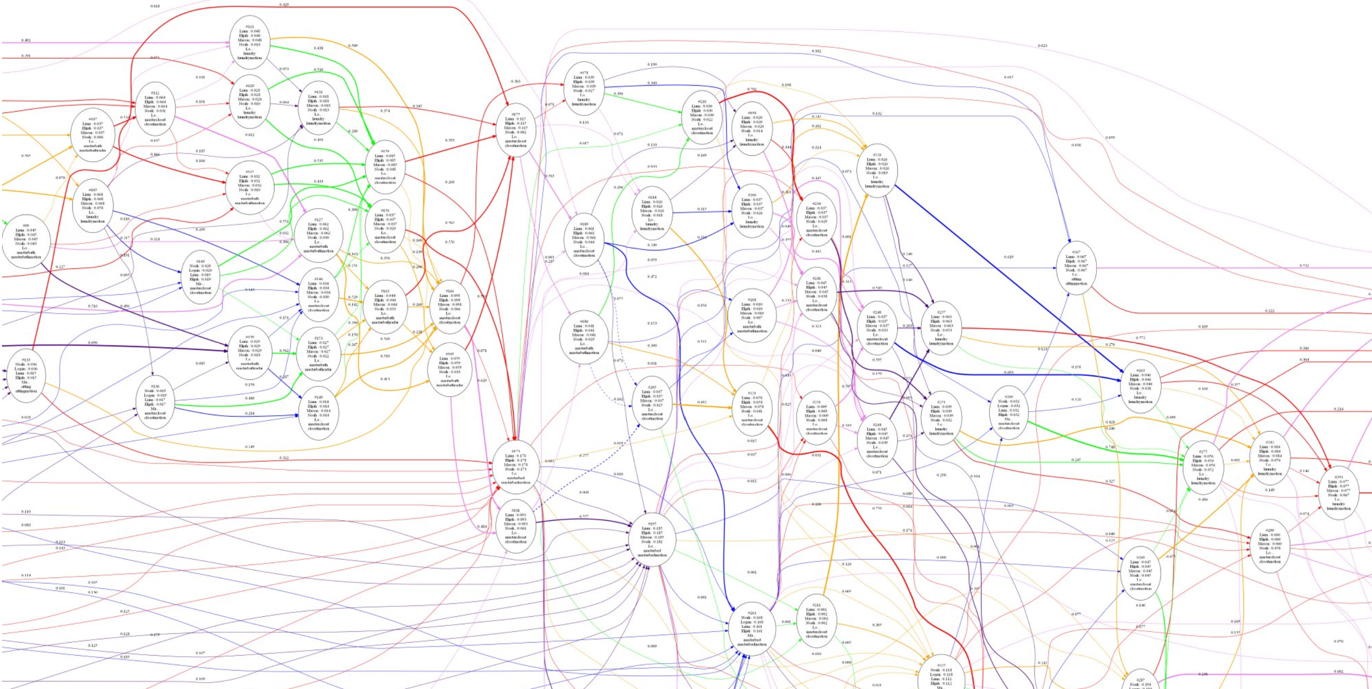
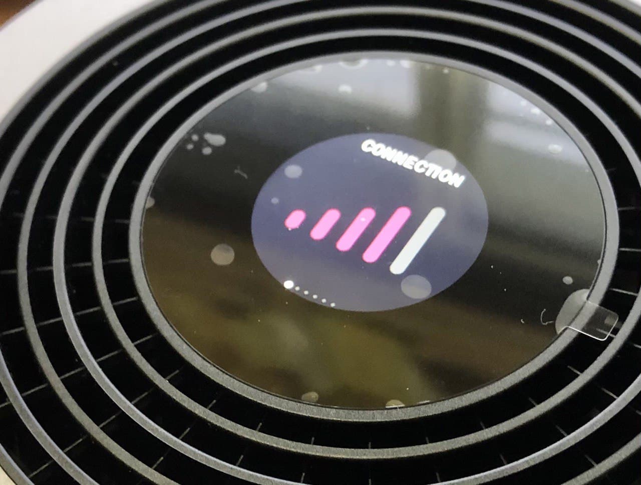
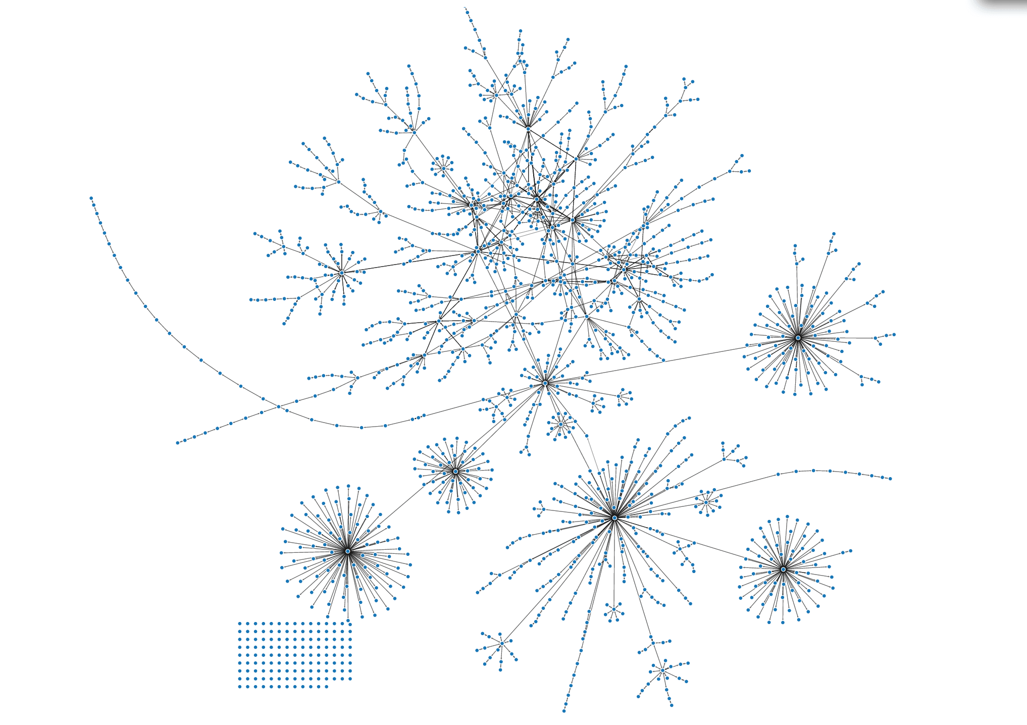
In addition to the actual sensor values you may want to track data about the gateway or node that manages the sensors, for example: available disk space, internal temperature, wifi signal strength, mesh connections, ... It's important that your digital twin system is able to handle the data about gateways as well as individual sensors and to understand the relationships between them. A graph model of the connectivity is useful for this purpose and can be essential for diagnosing problems, e.g. the temperature sensor isn't updating because the gateway has an intermittent WiFi connection.
You may need a state machine
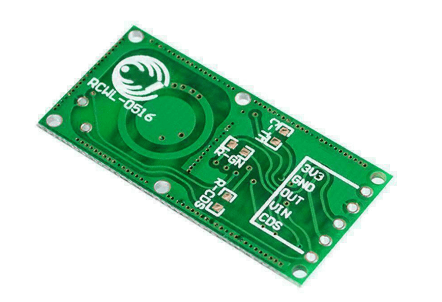
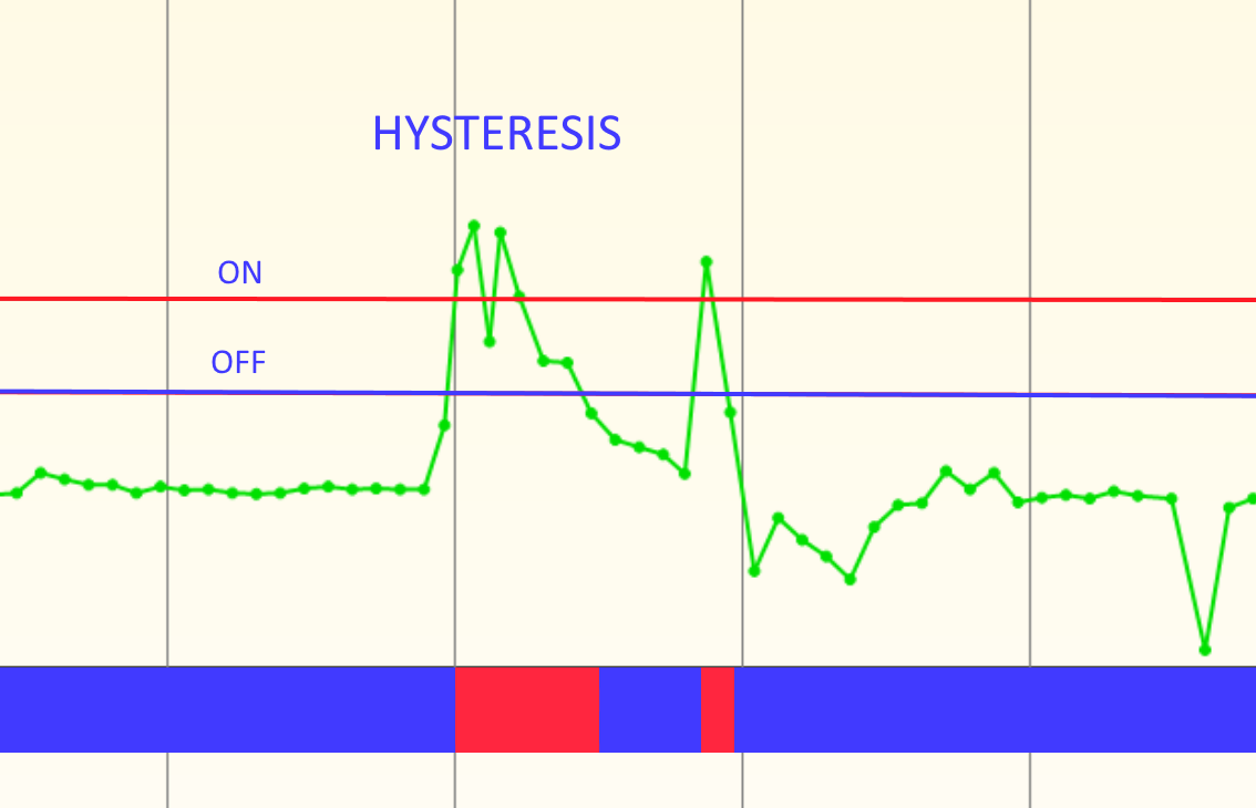
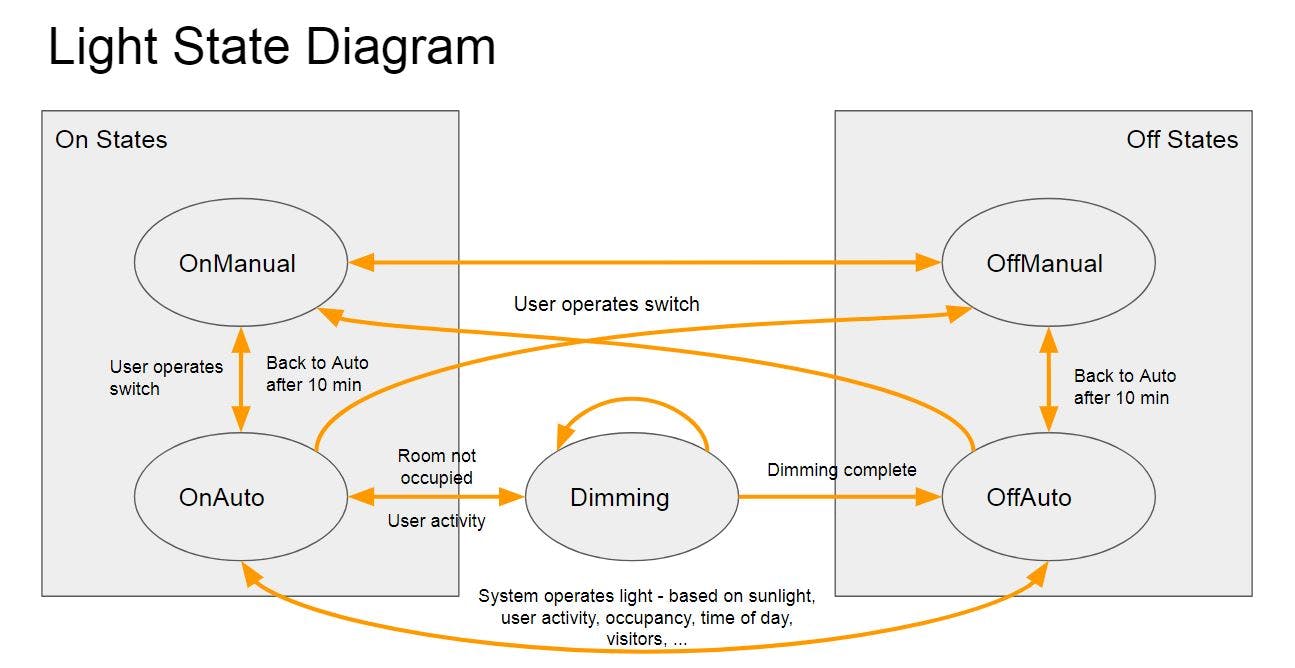
You may need a state machine on the input side and a different state machine on the output side. A refrigeration unit for example cannot be cycled on and off quickly without causing damage to it, you need to track state in order to enforce rules about how often it cycles. Some devices may have specific sequences they need to be put through to change a setting. Some protocols require a state machine to handle the messages: even a simple telnet protocol for example needs a state machine that handles disconnected vs connected states. State machines can also be used to condition digital inputs, like debouncing a noisy contact, or waiting for three pulses from a doppler radar sensor before concluding that it really is being triggered. I use my C# hierarchical state machine for these situations.
The digital twin may exist across several components
Azure IoT provides some limited digital twin capabilities and can reliably pass messages back and forth between devices and the cloud. You might use those capabilities and then build a richer digital twin with the techniques above using Azure functions triggered from Service Bus messages received by the IoT hub.
Summary
As you can see there's quite a bit of extra work to do beyond the naïve assumption that a digital twin is just a mirror of some values on a device with the same values in the cloud.
